Location of Vertical Sync and related Ground on 15pin HD video connector. For the Sync-doubler, remember to connect all straight through, except for pin 14 (Vsync), which is routed through the controller. |
|
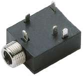
How to connect the Vsync signals to the 3.5 mm stereo plug for connection to the controller. |
|
Where to find L/R control and ground on the connector for the 25-pin parallel (LPTx) port, like for any LCDBIOS compatible application using this port. |
|
Where to find L/R control and ground on the connector for the 9-pin serial (COMx) port, like for the Cyberboy or any other LCDBIOS compatible application. |
|
Where to find L/R control and ground on the VESA 3-pin Mini DIN connector. Still not quite sure whether this is seen from front or back, but from what i read at stereo3d, you will hardly need this, anyway. |
|
How to connect the L/R control signal to the 3.5 mm stereo plug for connection to the controller. |
|
For open collector output using transistor Q2, find 'OC' label on smaller PCB, cut connection to IC3/pin7 (red lines) and connect signal to IC3/pin6 (green line) |
|