Power Sources at the PC
![]()
Power Sources at the PC |
|
Parts needed : commercial USB cable, length approx. 1-2 m (4-6 ft.), preferably A-A type.
Most PCs have USB ports these days, at least 2 of them, or even more. Even some monitors have built-in USB hubs, and since all we want here is power, you don't even need a USB connection between monitor and PC to use one of these. More information can be found at the Hardware Book's USB pages ( page #1 page #2 )
|
The bad news is, that it is (almost?) impossible to find single USB plugs to connect your own cable, so you will have to sacrifice a custom USB cable for this purpose. Try to get a 'A'-'A' cable, i.e. with flat plugs on both ends (see picture), though they may be a little hard to find, since they have hardly any purpose, but it will give you two supplies, so you could help a friend. The cheapest cable you can get will do, as long as you can get the power out of it. |
|
||||
|
According to the Hardware Book, the USB standard signal allocation and wire colors are : |
1 |
red |
+5V DC |
|
|
|
2 |
white |
Data - |
|||
|
3 |
green |
Data + |
|||
|
4 |
black |
GND |
|||
|
So, all you have to do is cut the cable to desired length and strip off the isolation and shielding (take care not to damage the wires' isolation). Then cut the green and white data wires short and (better) isolate their ends with tape or heat-shrink tubing. This will leave you with the red and black wire as +5V and GND for your circuit/adaptor. From the USB specification, it should support at least a few 100 mA. |
|||||
Parts needed :
D-Sub connector 15 pin male (PC gameport plug) and either :
corresponding plastic shell or
D-Sub connector 15 pin female (for gameport pass-through adaptor)
some cable, e.g. 0.5mm² speaker cable (maybe approx. 20 AWG ?)
So your PC hasn't got an USB port, or they
all are occupied by keyboard, mouse, joystick, monitor, scanner,
webcam, ... ?
Unless you got one of those new 'legacy-free' PCs,
you should have the good old analog joystick port somewhere on the
back of your computer. As I said, it has enough power to drive
force-feedback controllers, so it should have no problem to supply
your shutter glasses.
|
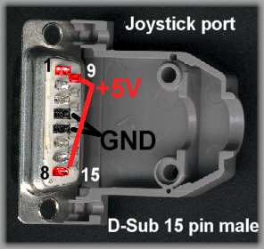
Again from the Hardware Book, the PC gameport has +5VDC on pins 1,8 and 9 and GND on pins 4 and 5. Pin numbers are stamped into the platic isolation of the connectors, so they should be easy to find, even more since you only have to find one of the outermost pins in the longer row for +5V and one of the two central pins in the same row for GND (see red and black dots in the drawing). If you don't need the gameport otherwise, all you need is a male Sub-D-15 connector, maybe with the corresponding plastic shell (see picture). Solder the wire for +5V to pin #1 (or #8, or even both #1 and #9) and, if needed, the wire for GND to pin #4 or #5 (or both). |
|
|
In case you still need the gameport for your joystick/wheel (or MIDI keyboard, or whatever..), you will need a pass-through adaptor. Get both a 15-pin D-Sub (or Sub-D) male and female connector and solder them back-to-back, connecting all corresponding pins (see picture). Solder the wire for +5V to pin #1 (or #8, or even both #1 and #9) and, if needed, the wire for GND to pin #4 or #5 (or both). Adding a little more solder (beware of short-circuits, of course) should make the stack sufficiently rigid, so you will hardly need any more mechanical parts for stabilization, except, maybe, for some isolation tape to wrap around the center part and protect the contacts from short-circuit by external metal parts. |
|
Parts needed :
D-Sub connector 9 pin female (like plug of serial mouse) with a pair of screws for mounting
plug resp. Y-splitter cable for PC hard disk/CD-ROM drive power supply
D-Sub connector 9 pin female with plastic shell to connect from the outside
again some cable
for additional output voltage :
78xx integrated voltage regulator, e.g. 7809 for 9 Volts
approx. 10µF/16V electrolytic capacitor (higher voltage or capacity is also OK)
(optional) heatsink for the voltage regulator
The last one is for those who are not afraid of working inside their computer, buying some electronics parts and soldering them together. It also helps if you have some low-power (~6-12 Volts, some 100mA, check the ratings that should be printed somwhere) peripheral device powered by a wall-plug supply which you always forget to turn on and off together with your computer (mine is a MIDI keyboard). Commercial versions of this are also available, but cost much more and usually take away an expansion slot in the backplane.
My version makes use of one of those spare openings for serial (and parallel) connectors that you usually find in your PC's backplane, covered with some piece of metal.
Before continuing, you will have to turn the PC off, remove the power cord (to make sure that there is definitely no more power) and open the case. Remove the cover from one of the smaller openings (small serial port size, you usually have to break it off).
|
|
|
|
The wiring for the PC 5.25“ power connector can be found at this page of the Hardware Book. The pin assignment on the 9-pin socket is completely my own personal standard. Complete circuit and wiring are shown in the schematics above. If you don't need a third voltage besides +5V and +12V, you can do as well without the voltage regulator and the capacitor. If you need a different voltage, take a 7806 (6V) or 7808(8V). |
|
|
|
|
|
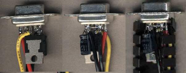
Building the adaptor shouldn't be too hard if you have a little experience in electronics soldering. Note that pins 6..9 (GND) are bridged with a piece of wire. IN and OUT of the regulator (outer pins) are soldered to pins 3 resp. 5 of the Sub-D socket, GND (center pin) to the wire between pins 8/9. Solder capacitor with (+) side to pin 5, (-) side to pin 9. |
|
|
Double-check that there is definitely no short-circuit between +12V(yellow) resp. +5V(red) and GND resp. the metal case of the connector. The heatsink must not touch anything but the back of the voltage regulator (you really wouldn't want to short-circuit a 250-300 W PC power supply) ! |
|
|
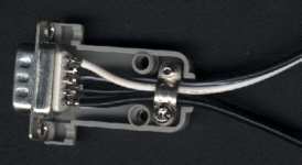
Sample plug to provide +5V/GND (bright cable, top) and +9V/GND (dark cable, bottom) supply to two external devices (Revelator adaptor and MIDI keyboard, in my version) |
|