DIY Revelator Dongle
![]()
DIY Revelator Dongle |
|
Parts needed :
Half
(or less, don't make it too long) of some old/spare VGA monitor or
Voodoo2 loop cable as a good starter. Using the male side will be
described here; converting the description to build a second adaptor
from the female side is left as an excercise to the reader
;-)
Otherwise a male HD-15 VGA connector with plastic shell and
some (~30 cm / 1ft.) VGA cable (15 wires, shielded – if you've
already used both ends of a longer cable for two adaptors, here's
the chance to save yet another friend with the remaining middle
part.).
A female (resp. male, for the other half of the VGA cable) HD-15 VGA connector with (metallized, if possible) plastic shell (usually used for 9-pin serial adaptors, see picture below).
A female mini-DIN3 connector to plug in the Revelator glasses resp. IR emitter.
One of the +5V DC supply solutions (I chose the version with the DIY PC power outlet here, since this is going to be the adaptor I'll be using most of the time).
Some
cable to connect the mini-DIN3 connector. You need three wires,
resp. two wires plus shield (e.g. stereo headphone cable), if you
join all cables in the VGA connector (as I did).
You may as well
get along with thin two-wire speaker cable for L/R control and GND
if you join the +5VDC supply in the mini-DIN3 connector (as in the
DIN3-passthrough
adaptor)
If you have started with half of an off-the-shelf VGA cable, the plugs are usually cast in plastic, so you will first need a cable tester (digital multimeter with Ohm-ranges, preferably with a beeper as contact indicator) to find out how wires and pins are connected – unless you were lucky and found a cable with two-part click-together plastic shells around the connectors. Wire colours and pin allocation is, of course, higly dependant on both raw and final cable brands, so it won't help anybody to publish my findings here, I'm afraid.
|
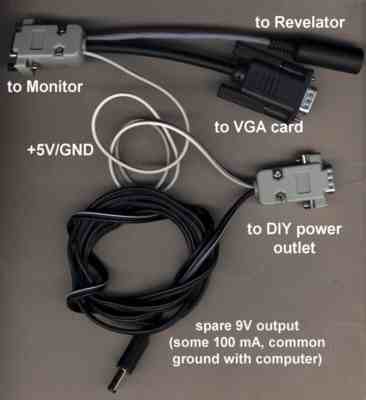
Here you see my personal DIY adaptor in all its beauty: The female VGA connector for the monitor, where all of the VGA cable from the PC (black), the three-wire cable to the mini-DIN3 socket for the glasses (gray) and the +5V/GND cable from my DIY power outlet (black/white) meet. The VGA cable with male connector is half of an old Voodoo2 loop cable. Not really worth mentioning here, but, as you can see in the picture (and read in the instructions), the DIY power port also provides another (regulated) +9VDC supply, which now feeds my MIDI keyboard (and also +12VDC from the PC power supply). |
|
|
Here's some more details about the internals of the VGA connector. Solder all wires of the VGA cable to their corresponding pins on the female VGA connector ('to monitor'), except pin #12 (Revelator L/R control) ! Instead, solder the wire from PC VGA-out pin#12 to the corresponding (L/R control) wire of the cable to the mini-DIN3 socket for the glasses, as well as +5V and GND from the power source. Note that I also took GND from the extra power source, just to avoid soldering two wires to one of the VGA connetor pins. Joining all cables in the VGA shell is quite a tight fit, so make sure that all loose wire connections are properly isolated (tape or heat-shrinking hose). You will also have to do a little work on the shell's cable outlet to make all cables get through. |
|
Well, there is one drawback when
building this adaptor – you'll end up with a spare, absolutely
useless, genuine ELSA adaptor ;-) If this should be a problem for
you, there is always the alternative to use the ELSA adaptor as the
base from which you build the DIY adaptor.
|
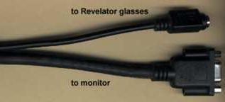
Cut the two cables where they meet at the plug for the PC VGA output, so you will get a female VGA connector (for the monitor cable) and a female mini-DIN3 connector (for the glasses – so you don't have to find one at the shop! ), each already connected to a sufficiently long cable stub. All you need now is a male VGA connector with plastic shell and the power source for +5VDC (and a cable tester, to find out which wire in the cables belong to which pin of the connectors). Be prepared to find three shielded wires (for R/G/B) in the VGA cable. |
|
In this case, as well as when you use the female end of another VGA (loop-) cable, you will of course need a male VGA connector (which plugs into the PC's VGA out) to build the adaptor. Then, solder the wire for L/R control of the glasses to pin #12 of the male connector, leave the wire to pin#12 for the monitor unconnected (cut short) and connect the remaining wires of the VGA cable to their corresponding pins.