DIN3 Cable Splicing
![]()
DIN3 Cable Splicing |
|
An (almost) no-parts solution. However, you will have to do some harm to your original Revelator adaptor. The idea is to find the wire that should get the +5V from VGA pin #9 (but doesn't) in the thinner cable between the VGA plug and the mini-DIN3 socket for the glasses and connect that to the external +5V power source.
The other bad news is that I didn't dare to do this to my adaptor, so you have to find the correct wire by yourself, using a cable tester/Ohmmeter/Digital multimeter. From data sheets for the AWM 2464 cable that I found on the web, the core wires may/should be red, brown and black. If I were ELSA, I had made +5VDC red, GND black and L/R brown, but you never know...
Another con: It won't help you with DDC problems caused by the monitor driving the DDC line.
Yes, I said I didn't dare to do any harm to my adaptor – the pictures below are just for illustration, using some piece of junk cable. Don't expect to find green and white wires in the real Revelator adaptor !
|
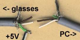
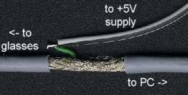
As 'brute force' approach, just cut the thin cable between the VGA plug and the glasses socket, somewhere in the middle. |
Remove some of the outer plastic jacket and put aside the shielding to access the (most likely 3 plus one blank) core wires. Identify the wire connected to pin #9 of the VGA plug. |
|
|
|
|---|---|
|
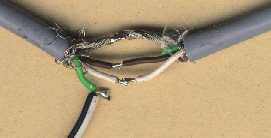
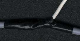
At the cut-off part with the DIN3 socket, solder this wire to your +5V source, and reconnect the other two wires and the shielding. |
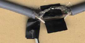
Use some tape to isolate the junctions from each other and the shielding and coat the whole junction for better stability. |
|
|
|
|
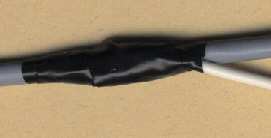
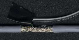
The gentle way would be to carefully remove some (~ 2cm/1 in.) of the outer plastic jacket of the cable, revealing the shielding layer. See pictures of how I did this with some other piece of junk cable, still just for illustration. Next, try to locate the core wires through the shielding and find the one connected to pin #9 of the VGA plug, e.g. piercing the wires' isolation with a pin (I'd start with the red one, if there is any). Cut the correct wire close to the PC side of the gap, so that you can take some of the end leading to the DIN3-socket out of the cable's core and solder it to your +5V supply wire. Isolate carefully with some tape and you should be done. |
|
|
|
|
|
|